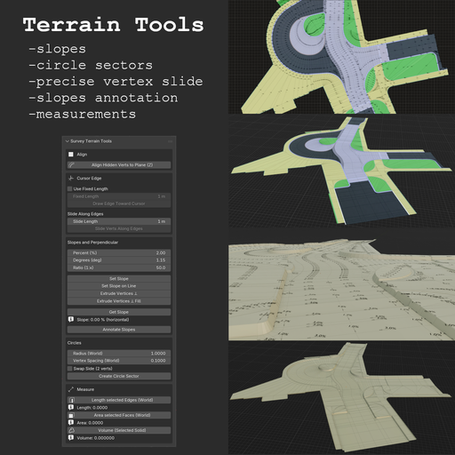
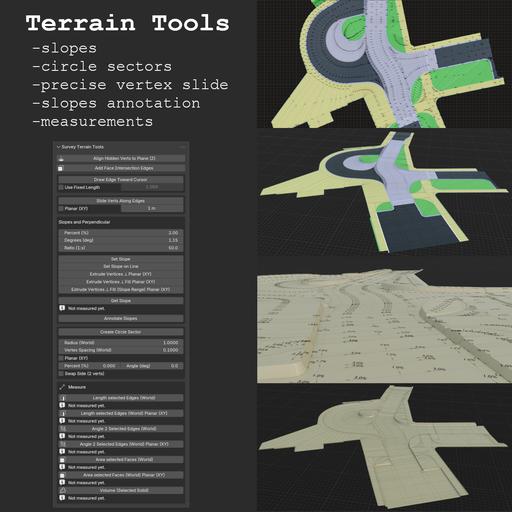
Survey Terrain Tools – Geodetic & Construction Workflow
Survey Terrain Tools is a terrain-focused Blender add-on designed for fast, precise, and practical mesh workflows used in survey, civil-engineering, and CAD-style modeling.
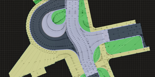
Terrain-focused modeling and measurement toolkit for fast survey/CAD-style mesh workflows.
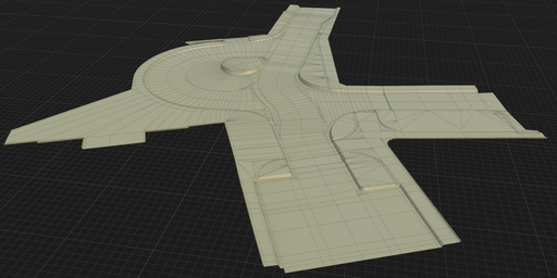
Designed for production use: deterministic tools, world-space measurements, and predictable geometry creation.
Why This Add-on- Hidden-vertex alignment with Align Hidden Verts to Plane (Z)
- Cursor-driven edge creation and controlled vertex sliding
- Slope workflows for single edits, line batches, and perpendicular extrusions
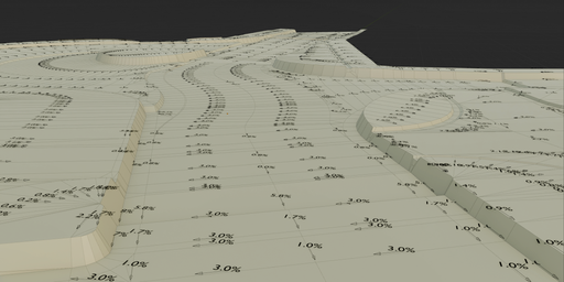
- Slope annotation labels and drop-direction arrows (Annotate Slopes)
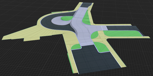
- Practical circle-sector construction (2-point and true 3-point)
- World-space measurement tools (length, area, volume) and face-plane intersection edges in one panel
- Minimal setup, no external Python dependencies
- Align Hidden Verts to Plane (Z)
- 2 verts: computes Z from a vertical-plane rule in XY
- 3 verts: projects hidden vertices along Z to the infinite plane defined by the 3 selected verts
- Workflow: hide vertices you want to align, keep reference vertices visible and selected, then run the operator
- Useful when pulling geometry in XY first (for example from ortho/reference edges) and resolving final Z/slope afterward
- Add Face Intersection Edges
- Edit Mode: select two or more faces (adjacency not required)
- For each pair of faces, intersects their supporting planes and adds one edge along the overlap clipped to both faces; faces are not deleted
- Works best on convex faces; concave ngons may miss segments or clip incorrectly
- Draw Edge Toward Cursor
- Modal viewport tool with preview line
- Works in Edit Mode from active/selected vertex
- Uses panel values: Use Fixed Length + Fixed Length
- Enables line creation at arbitrary mouse-defined angle with precise length control
- Creates one new vertex and one connecting edge on confirm
- Slide Verts Along Edges
- Slides selected vertices along exactly one connected visible edge
- Uses dedicated panel values: Slide Length and optional Planar (XY) (world XY projection / plan view)
- Default: exact slide distance along the 3D edge (world-space length)
- With Planar (XY): Slide Length is the length of the world XY projection of the move (still along the 3D edge); purely vertical-in-XY edges are skipped
- Ignores hidden edges when checking connectivity
- Vertices that do not match the one-edge rule are skipped
- Set Slope
- 2 selected vertices, applies Z offset on active vert from current slope inputs
- Set Slope on Line
- Batch tool: supports isolated selected edges or one connected open line
- Extrude Vertices ⊥ Planar (mesh XY)
- Extrudes selected vertices along the angle bisector (miter) of connected edges
- Builds offset line from the selected line/loop with adjustable slope on created edges
- Planar (mesh XY): edge directions are projected to local XY (plan view in mesh space); slope “run” is distance in that plane (not world-ground unless the object is aligned)
- Angle Correct Length compensates corner angles so offset width stays more uniform at bends
- Extrude Vertices ⊥ Fill Planar (mesh XY)
- Same as above, plus side-face fill between neighboring extrusions
- Supports one open non-branching line and one closed non-branching loop
- Extrude Vertices ⊥ Fill (Slope Range) Planar (mesh XY)
- Like Extrude Vertices ⊥ Fill, but slope varies linearly from Slope from (%) to Slope to (%) along the line
- Requires one open non-branching line (exactly 2 endpoints); no loop
- Active endpoint gets Slope to; opposite endpoint gets Slope from
- Dialog: Slope from (%), Slope to (%), Swap From/To (swap from/to in computation)
- Get Slope
- Reads slope from 2 selected vertices and writes result below the button
- Annotate Slopes
- Creates slope text + drop-direction arrows at edge midpoints (in a new collection)
- Processes all mesh edges (with optional length filter in dialog)
- Label format selectable in operator dialog: Percent (%) or Ratio (1:x)
- Create Circle Sector
- 2 verts: arc between selected endpoints using Radius (World)
- When distance > 2R, radius is remapped internally for computation only, major arc is used, and side is flipped internally for stable behavior
- Default is 3D (tilted arc plane). Enable Planar (XY) to force plan-view arc generation in world XY
- Tilt can be entered as Percent (%) or Angle (deg) (synchronized); ignored in 3-vertex mode
- 3 verts: true 3D circle from all selected points; generated arc passes through all three selected vertices
- Vertex Spacing (World) controls tessellation density
- Length selected Edges (World)
- Length selected Edges (World) Planar (XY) — sum of edge lengths in world XY (plan view; vertical-in-XY edges contribute 0)
- Angle 2 Selected Edges (World) — smaller angle between two selected edges as lines in 3D (world); adjacency not required
- Angle 2 Selected Edges (World) Planar (XY) — smaller angle after projecting both edges to world XY (plan view)
- Area selected Faces (World)
- Area selected Faces (World) Planar (XY) — sum of face areas projected onto world XY (plan view)
- Volume (Selected Solid)
Results are shown directly in UI and suitable for quick iterative checks.
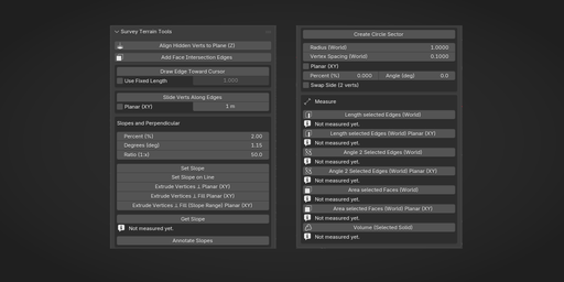
UI Location3D Viewport -> N Panel -> Survey -> Survey Terrain Tools
Sections:
1. Align
2. Faces
3. Cursor Edge
4. Slopes and Perpendicular
5. Circles
6. Measure
- Open Blender (5.0+).
- Go to Edit -> Preferences -> Get Extensions -> arrow in the upper right corner → Install from Disk.
- Select the ZIP file and Click Install from Disk.
- Blender 5.0.0+
- No external Python packages
- Email: jan.holinka@seznam.cz
GPL-3.0-or-later
VersionCurrent version: 1.1.0
Detailed history: CHANGELOG.md
Version: 1.1.0
Blender: 5.0.0+
Overview
Survey Terrain Tools provides terrain-focused modeling and measurement tools in one panel.
Panel location:
3D Viewport -> N panel -> Survey -> Survey Terrain Tools
Align Align Hidden Verts to Plane (Z)
- 2 verts: computes Z from a vertical-plane rule in XY
- 3 verts: projects hidden vertices along Z to the infinite plane defined by 3 selected verts
- Typical workflow: hide vertices to align, keep reference verts visible+selected, run operator
Faces Add Face Intersection Edges
- Edit Mode, two or more faces selected (they do not need to share an edge or vertex)
- For every pair of selected faces, builds the line where their planes meet and adds a new edge along the part that lies on both faces (in the mesh)
- Faces are left unchanged (no deletion); only new vertices/edges may appear
- Most reliable on convex faces; concave ngons can produce wrong or missing segments
Cursor Edge / Slide Draw Edge Toward Cursor
- Modal viewport tool with preview line
- Works in Edit Mode from active/selected vertex
- Uses panel values: Use Fixed Length + Fixed Length
- Supports arbitrary mouse-defined angle with precise length control
- Creates one new vertex and one connecting edge on confirm
- Slides selected vertices along exactly one connected visible edge
- Uses panel values: Slide Length and optional Planar (XY) (world XY / plan view)
- Default: exact entered distance along the 3D edge (world-space length)
- Planar (XY): Slide Length applies to world XY–projected displacement (movement still follows the edge in 3D); edges with no XY component in world are skipped
- Ignores hidden edges when checking connectivity
- Non-matching vertices are skipped
Slopes and Perpendicular Shared slope inputs
- Percent (%)
- Degrees (deg)
- Ratio (1:x)
These values are synchronized.
Set Slope- 2 selected vertices
- Applies Z offset on active/last-selected vertex using current slope inputs
- Batch mode
- Supports isolated selected edges or one connected open line
- Extrudes selected vertices along angle bisector (miter) of connected edges
- Builds offset line from selected line/loop with adjustable slope on created edges
- Planar (mesh XY): offset and slope “run” use local XY (edges projected to the mesh XY plane), not world axes unless the object is aligned to the ground
- Angle Correct Length compensates corners to keep offset width more uniform
- Includes Swap Sides
- Same as above, plus side-face fill between neighboring extrusions
- Supports one open non-branching line and one closed non-branching loop
- Like Extrude Vertices ⊥ Fill, but slope varies linearly from Slope from (%) to Slope to (%) along the line
- Open line only: select one non-branching open line (exactly 2 endpoints); loops are not supported
- Orientation: active endpoint = Slope to; opposite endpoint = Slope from
- Dialog: Slope from (%), Slope to (%), Swap From/To (swap from/to in computation)
- Reads slope from 2 selected vertices
- Writes result directly below the button in UI
- Creates slope text + drop-direction arrows at edge midpoints
- Texts and arrows are always created in a new collection
- Processes all mesh edges (optional length filter in dialog)
- Label format in dialog: Percent (%) or Ratio (1:x)
Circles Create Circle Sector 2 selected vertices
- Creates arc between selected endpoints using Radius (World)
- If distance > 2R, radius is remapped internally for computation only
- In remap mode: major arc is used and side is flipped internally for stable behavior
- UI/Redo still shows the user-entered radius value
- Default is 3D (tilted arc plane). Enable Planar (XY) to force plan-view arc generation in world XY
- Tilt can be entered as Percent (%) or Angle (deg) (synchronized); ignored in 3-vertex mode
- Vertex Spacing (World) controls tessellation density
- Solves true 3D circle from all selected points
- Generated arc passes through all 3 selected vertices
- Active vertex does not control arc orientation
Measure (World Space) Length selected Edges (World)
- Sums world-space lengths of selected edges
- Sums lengths of selected edges projected onto world XY (plan view; edges vertical in world XY contribute 0)
- Requires exactly 2 selected edges in Edit Mode
- Reports the smaller angle between the two lines in 3D (world space); whether the edges share a vertex does not matter
- Requires exactly 2 selected edges in Edit Mode
- Projects both edge directions onto world XY (plan view) and reports the smaller angle
- If an edge has zero planar (world XY) length, the operator reports an error
- Triangulates selected faces (nondestructively) and sums world-space area
- Triangulates selected faces (nondestructively) and sums their area projected onto world XY (plan view)
- Computes volume from selected faces
- Selection must be a closed shell
Troubleshooting Tool does not run
- Active object must be a Mesh
- Selection count/type must match tool requirements
- Most tools require Edit Mode
- 2-point mode under 2R enters internal remap mode (warning shown)
- Very small spacing with very large effective radius may hit segment safety cap
- 3-point mode requires non-collinear points
- Use vertices with exactly one visible connected edge
- Hide edges to exclude them from slide eligibility
- Selection must be one open non-branching line (exactly 2 endpoints)
- Loops and branching selections are not supported
- Selected faces must form a closed shell
- Each boundary edge must belong to exactly 2 selected faces
Release Notes
See CHANGELOG.md for version history.